Rectifier Circuits: Half‑Wave, Full‑Wave, and Bridge
Explore half‑wave, full‑wave, and bridge rectifiers; change diode drop and add a capacitor to see AC‑DC…
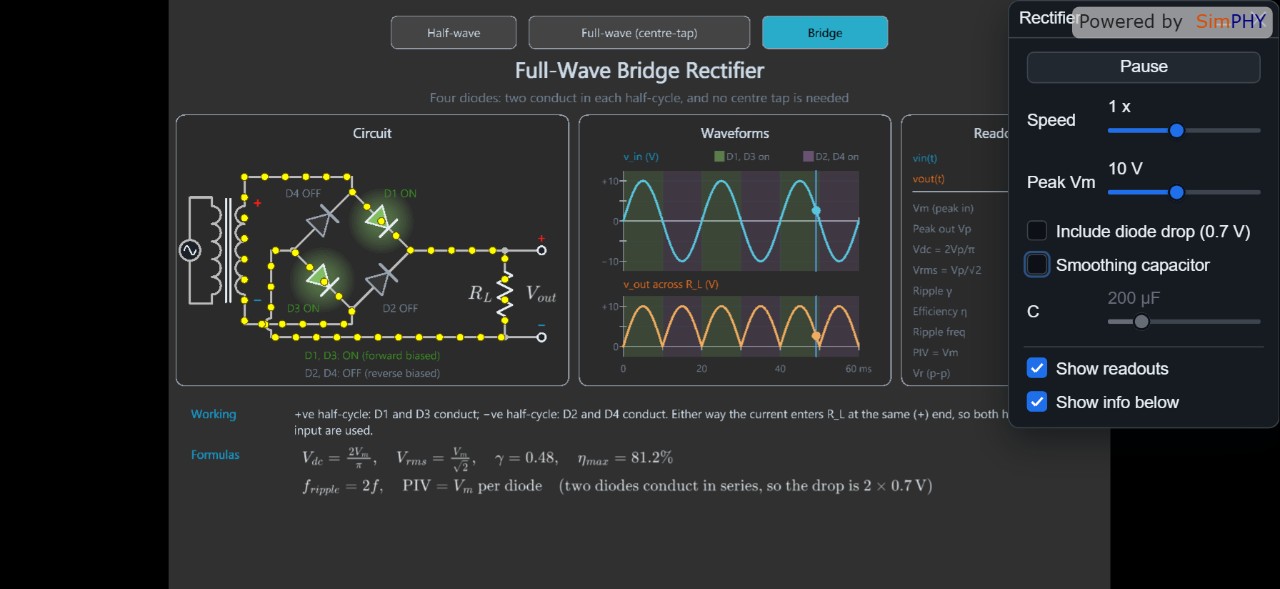
This simulation shows three common rectifier configurations – half‑wave, full‑wave (centre‑tap) and bridge – converting a 50 Hz AC source into a pulsating DC voltage. Diode forward voltage drop and an optional smoothing capacitor are modelled, so students can see how each element shapes the output and introduces ripple.
Tabs at the top let users pick the rectifier type. A dialog provides sliders for peak input voltage, diode drop (≈0.7 V), and capacitance of the smoothing capacitor. The circuit view animates current flow with moving dots, highlights conducting diodes, and displays instantaneous voltage and current values. A synchronized waveform panel plots the input AC and the rectified output, with shaded bands indicating diode conduction periods.
By adjusting the parameters, learners observe how a full‑wave bridge yields twice the ripple frequency of a half‑wave rectifier, how the diode drop reduces the peak output, and how increasing capacitance smooths the voltage. The activity reinforces concepts of AC‑DC conversion, diode behaviour, ripple reduction, and basic power‑electronics principles.
Related Simulations
 Free
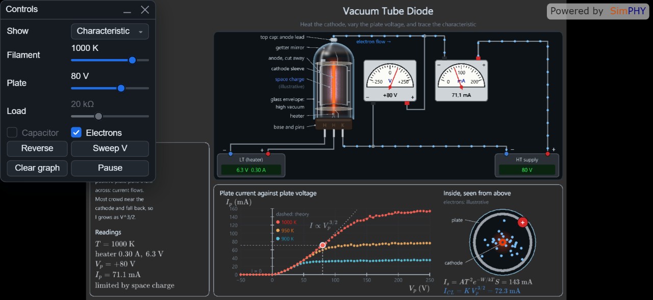
Vacuum Diode: Thermionic Emission and Half‑Wave Rectification
ElectronicsExplore thermionic emission and half‑wave rectification by adjusting f...
 Free
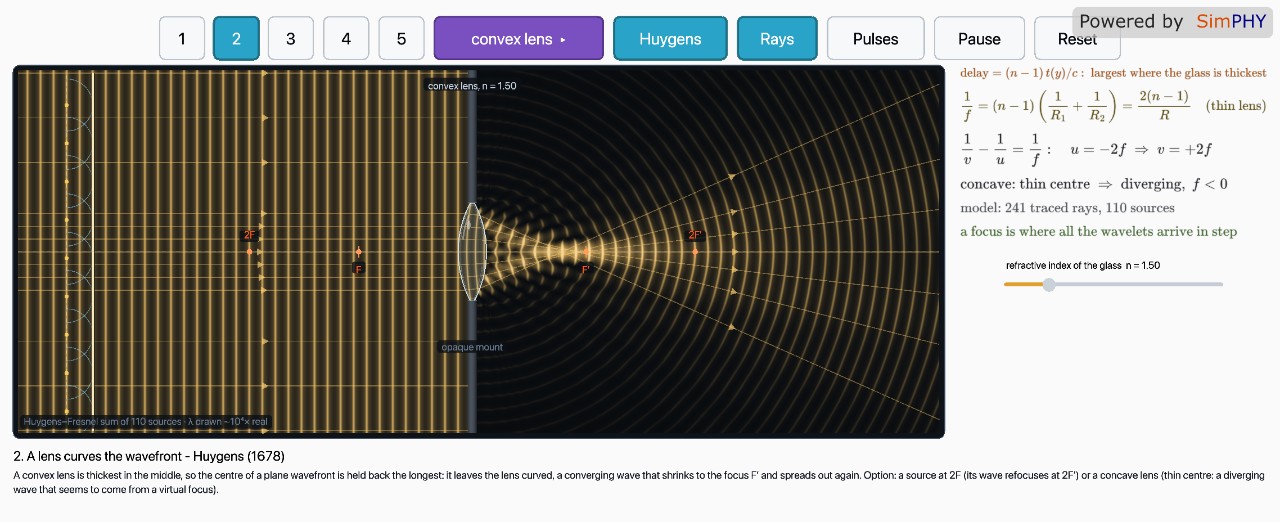
Wavefronts Through Optical Devices
Rotational MotionExplore Huygens’ construction and ray behavior as wavefronts pass thro...
 Free
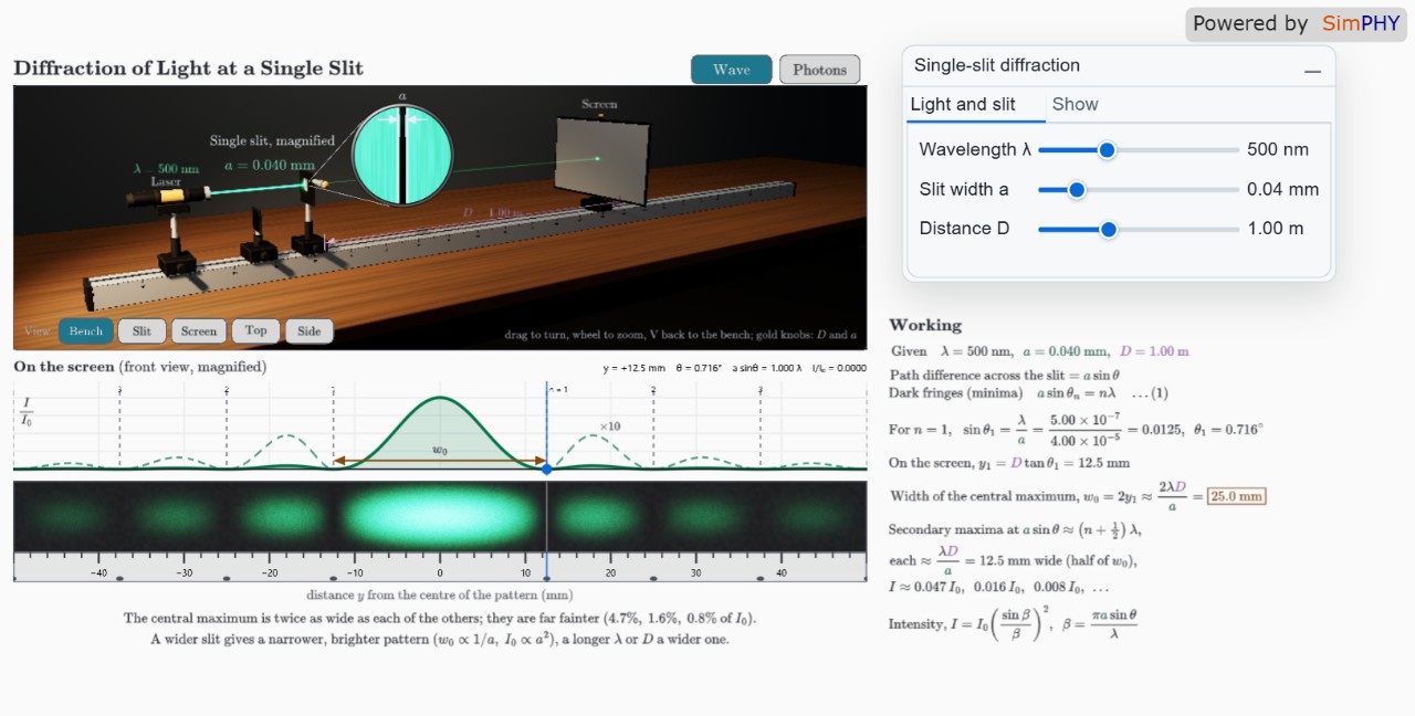
Diffraction of Light at a Single Slit
Wave OpticsExplore how slit width, wavelength, and distance affect the Fraunhofer...
 Free
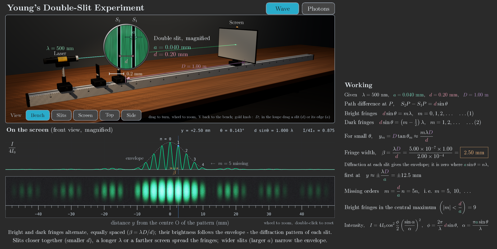
Young's Double‑Slit Experiment
Wave OpticsObserve interference and diffraction from a laser through adjustable s...